There are many different parts of the electric motor, today we will talk about some knowledge about the rotor of the electric motor.
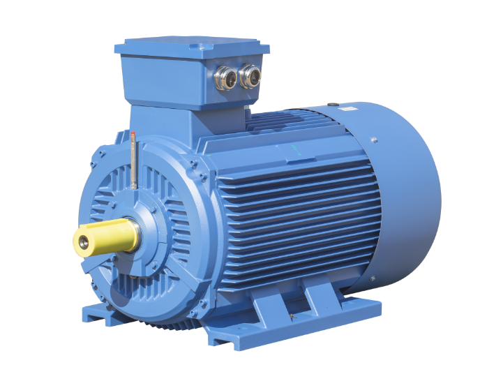
Why does the electric motors rotor have an oblique groove?
In order to improve the quality of electric motors, induction motor noise has been included in one of the quality assessment indicators in recent years, especially for the electric motor operating environment and close contact with people, the noise of the electric motor has become a very important assessment requirements.
In order to control the asynchronous induction motor noise, in addition to the design of the selection of suitable stator-rotor slot fit.
It can be used to reduce the electromagnetic noise of the electric motor slope of the slot.
But exactly how much slot slope is more appropriate, it is necessary to further test verification.
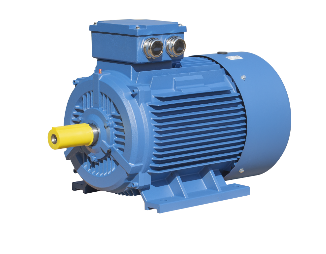
In general, the asynchronous electric motor rotor slot slope can be taken as one stator tooth pitch, which can also basically meet the requirements.
However, in order to further improve the electric motor noise, the optimal slot slope needs to be explored, which requires a lot of calculations and verification.
From the manufacturing point of view, the straight slot electric motor is relatively simple to produce and process, but when necessary, it is necessary to twist the stator slot or rotor slot.
It is relatively difficult to twist and bevel the induction motors stator slot, so in most cases, the rotor slot is beveled.
The twisting of the rotor slot is usually achieved by machining the twisted keyway on the motor shaft, or for more advanced companies, by using a spiral punch, which is realized in the rotor core manufacturing process.
Electromagnetic noise generation causes and avoidance measures
Motor noise has been a difficult problem to solve, it is mainly generated by electromagnetic, mechanical and ventilation three reasons.
Electromagnetic noise in the asynchronous motor is generated by the electromagnetic force wave caused by the interaction of the harmonic magnetic field established by the stator windings and rotor currents in the air gap, which causes the core yoke to vibrate and forces the surrounding air to vibrate.
The main reason is due to improper slot fit, stator and rotor eccentricity or air gap is too small, etc.
Electromagnetic noise is caused by the magnetic pull acting between the parts of the electric motors that make changes in time and space and is caused by the magnetic poles pull acting between the parts of the ac motor.
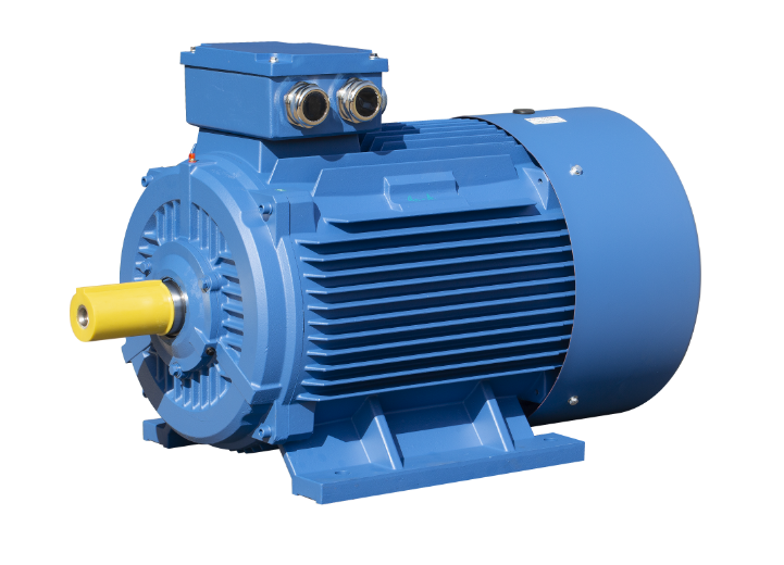
Therefore, for asynchronous motors, the causes of electromagnetic noise formation include.
● Radial force waves in the air-gap space magnetic field cause radial deformation and periodic vibration of the stator winding and squirrel cage rotor.
● Radial force waves of high harmonics in the air gap magnetic field act on the stator and rotor cores, causing them to deform radially and vibrate periodically.
● The deformation of stator cores with different order harmonics have different inherent frequencies, and resonance is caused when the frequency of radial force wave is close to or equal to some inherent frequency of the core.
● The deformation of the stator causes the surrounding air to vibrate, and most of the electromagnetic noise is load noise.
When the core is saturated, the third harmonic component is increased and the electromagnetic noise is increased.
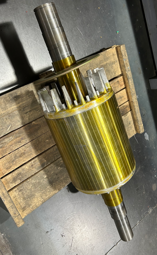
The smaller the air gap is, the wider the slot is, the larger their amplitude is.
To avoid this problem, we should improve the product design stage by some effective means, such as: choosing a reasonable flux density, choosing the right winding type and the number of associated roads, increasing the number of stator punching slots, reducing the harmonic distribution coefficient of the stator winding, proper processing of the stator-rotor air gap of the motor, choosing the stator and rotor slot fit, using the rotor slant slot and other specific measures.
Why are cast aluminum rotor electric motors universally accepted for the electrical energy?
According to the characteristics of the material filled in the slots of the motor rotor, there are wire-wound rotors, cast aluminum rotors and permanent magnet rotors.
In comparison, cast aluminum rotors are the most widely used, certainly due to some of the cost and process advantages of this type of rotor about the mechanical energy.
The slot shape of cast aluminum rotor is not restricted by the profile, and the best slot shape can be chosen arbitrarily to improve the starting performance of the three phase induction motors.
The rotor copper row accounts for about 40% of the copper used in the whole standardized motors, and the use of cast aluminum rotor windings can greatly reduce the material cost of the industrial motors.
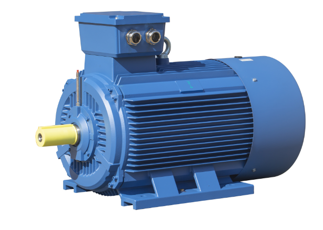
The cast aluminum conductor fills the whole rotor winding slot, and the slot full rate is close to 100%, which is conducive to heat conduction and dissipation.
The rotor air blade and end ring are cast together to increase the heat dissipation capacity, and there is no need to install another fan, which saves some processing procedures.
The structure of the cast aluminum rotor is symmetrical and compact, and the balance column and end ring are cast together, which is easy to obtain the balance mechanically; the production cycle is short, the working hours are low, and the cost is low, which is suitable for mass production.
However, a cast aluminum rotor is not a panacea for everything, for example, for high efficiency and high power motors, a copper bar rotor or cast copper rotor may be required to achieve this.
The punching system's quality directly affects the pressed core's quality.
The uneven shape of the groove will affect the quality of the embedded wire; the burr is too large, the size of the teeth is too large and the accuracy of the core size, tightness, etc. will affect the magnetic conductivity and loss.
Punching quality control of ac motors' rotor
The quality of the punching sheet is a problem.
The size of the punching sheet is not good, resulting in uneven magnetic density of the stator and rotor teeth, which increases the excitation current, increases iron consumption, low efficiency and low power factor.
Accuracy of punching size.
The accuracy of the size, coaxiality and slot position of the punching sheet can be ensured from the silicon steel sheet, punching die, punching scheme and punching machine. From the die side, reasonable clearance and die manufacturing accuracy are necessary to ensure the accuracy of die size.
Punching and shearing process problems and their effects
● The indexing plate is not allowed, and the position and size of each tooth on the plate are not consistent due to wear, so that the groove distance on the punching sheet is not the same, and the phenomenon of small and large tooth distance appears.
The rotating mechanism of the slot punching machine does not work properly.
For example, changes in clearance, lubrication and friction can cause changes in the size of the rotating angle and affect the uniformity of the slot position of the punching sheet.
●The positioning mandrel of the punching plate is worn out and the size becomes smaller, which will cause the radial shift of the slot position.
This will cause the groove to be unevenly shaped when the core is stacked, and will cause mechanical imbalance to the rotor punch.
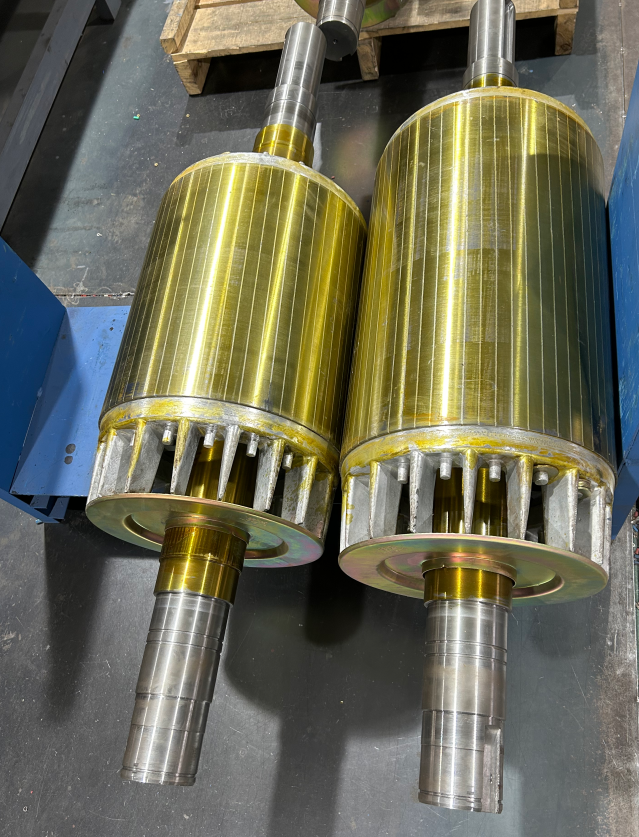
● Wear of the key on the mandrel also causes the offset of the groove.
Key wear increases the clearance between the key and the keyway of the punch, resulting in the offset of the groove.
The offset increases as the punch diameter increases.
If the outer circle is used for positioning, this offset does not occur and the quality of the punch is better than if the punch is positioned with a shaft hole.
● Burrs, which cause short-circuiting between the sheets of the core, increase iron consumption and temperature rise.
The presence of burrs reduces the number of punches, causing an increase in excitation current and a decrease in efficiency.
The burr in the slot will pierce the insulation of the winding, and will also cause external expansion of the teeth.
When the burr at the rotor shaft hole is too large, it may cause a reduction in hole size or ovalness, resulting in difficulties in press fitting the core on the motor shaft.
Excessive die clearance, incorrect die installation or blunt die edges can cause burrs in the punching sheet.
To reduce the burr, it is necessary to strictly control the clearance between the punch and the concave die during the manufacture of the die; to ensure uniform clearance on all sides during the die installation; to ensure the normal operation of the die during the punching process, to check the size of the burr frequently, and to repair the edge in time.
● Punching sheet is not flat and clean.
When the punching sheet has corrugations, rust, oil, dust, etc., it will make the press fitting coefficient lower.
When press-fitting, control the length for rotor and stator.
Too many pieces will make the core weight insufficient, reduce the magnetic circuit section and increase the excitation current.
Poor insulation treatment or poor management of the punching sheet, the insulation layer is destroyed after press-fitting, so that the core short circuit, eddy current loss increases.
Dynamic balancing problem of rotor with fan
Ventilation is an important part of the ac motor, ventilation effect on the most electric motors temperature rise, vibration and noise and other performance effects; from the structure of the ac motor rotor, from and fan settings have different requirements; some motor rotors do not have a fan, including the cast aluminum rotor air blades are not.
Some ac motors only set the wind blades on the cast aluminum rotor, while some rotors will also set the rotor fan inside and outside the fan.
Our topic today is limited to the balancing of rotors with fans.
Theoretically, if the fan has been statically balanced before installation, the rotor shaft has been dynamically balanced before sleeving the core, and the rotor has been similarly dynamically balanced before installation of the fan.
Then, after the installation of the fan, the unbalance of the rotor should be relatively small, and in the later repair and maintenance, the fan is basically a part that meets the requirements and has interchangeability.
However, many electric motor manufacturers, the shaft, fan and overall rotor balance, all after the installation of the fan, so it seems to be less trouble.
But it is difficult to distinguish which associated parts are caused by the imbalance.
Of course, it is also difficult to prescribe the right medicine, and is not conducive to the later maintenance.
Why rotors are dynamically balanced
High-speed rotating machinery by the impact of the material, impact, corrosion, wear, coking will cause unbalance failure of the machine's rotor system for electric machine.
And 70% of the vibration failure of rotating machinery from the unbalance of the rotor system.
Usually, maintenance personnel for the larger vibration of the rotor, dismantling treatment, direct replacement of the impeller, etc., re-installed after operation, to reduce the purpose of vibration.
However, due to the existence of the original unbalance of the rotating parts, the vibration sometimes exceeds the standard allowable value even after the machine is running.
In order to prevent the destruction of the machine mechanical power, threaten the safety of the site personnel and ensure the normal operation of production, it is necessary to carry out dynamic balance correction .
Principle of dynamic balancing
The unevenness in the rotation of the rotor is caused by the fact that the center of mass of each micro-segment of the rotor is not strictly on the axis of rotation.
The centrifugal force generated by the deviation of the center of mass of each micro-segment from the axis of rotation is perpendicular to the axis of rotation.
The centrifugal force system can be synthesized into a few concentrated forces by force synthesis, whose direction is still perpendicular to the axis.
Generally speaking, at least two concentrated forces acting on two cross-sections are required to represent the original centrifugal force system.
If these two concentrated forces happen to form a force couple, the original imbalance cannot be detected and measured when the rotor is not rotating.
It is only when it is rotating that the force couple forms a lateral disturbance and causes the rotor to vibrate.
The effect of this imbalance can only be detected and measured in the dynamic of rotation, so dynamic balancing is required.
In contrast, static balancing is the balancing that can be performed without rotation when the mass of the rotor is so concentrated that it can be considered as a thin disk with no thickness perpendicular to the axis of rotation.
This is done by placing the rotor horizontally, with the weighted side hanging down by gravity, and trying to adjust the position of the rotor's center of mass so that it lies on the axis of rotation.
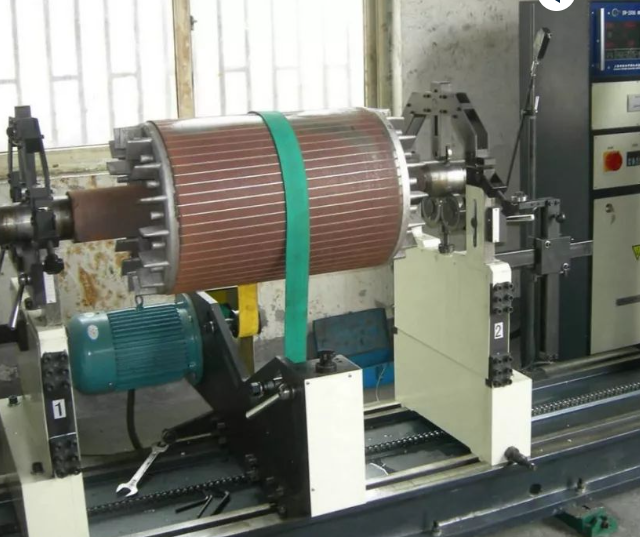
After measuring the location and size of the imbalance, either remove it directly or add the corresponding mass to balance its effect in its symmetrical direction, i.e., complete the dynamic balance by de-weighting or counterweighting.
Καλώς ήρθατε να αφήσετε μήνυμα στην περιοχή των σχολίων για οποιαδήποτε πληροφορία σχετικά με τους ηλεκτρικούς κινητήρες.
Οποιαδήποτε ερώτηση σχετικά με τον ηλεκτρικό κινητήρα, επικοινωνήστε με τον ΚΟΡΥΦΑΙΟ κατασκευαστή ηλεκτροκινητήρα στην Κίνα-Dongchun κινητήρα ως εξής.

Ο κινητήρας Dongchun διαθέτει ένα ευρύ φάσμα ηλεκτρικών κινητήρων που χρησιμοποιούνται σε διάφορες βιομηχανίες όπως οι μεταφορές, οι υποδομές και οι κατασκευές.
Λάβετε μια άμεση απάντηση.


