 Skip to content
1. The physical principle of electric motor work
1.1 Maxwell's system of equations
The electric motor is a transducer that constantly converts electromagnetic energy and mechanical energy.
When electrical energy is input, the electric motor can continuously output torque and mechanical energy.
i.e., the electric motor; conversely, if an external force continuously pushes the electric motor shaft and inputs mechanical energy, the electric motor can continuously output voltage and electrical energy from the wire end in reverse, i.e., the generator.
Historically, the static transformer was also counted as an electric motor, but it gradually evolved to refer exclusively to electric motors and generators.
One of the advantages of electric motors is that their losses are relatively small, so they achieve high efficiency.
Large electric motors can achieve efficiencies of up to 99%.
When talking about electromagnetic systems, Maxwell's system of equations is inevitable.
In the macroscopic world and even in the microscopic world,
Maxwell's system of equations can be used very effectively to describe the system properties.
Maxwell's system of equations has been summarized from previous studies of electromagnetic phenomena.
There are four very basic equations, both in differential and integral form.
Now let's examine Maxwell's system of equations in integral form.
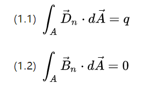
The above two equations describe the flux of the field density, respectively, the total of the outflow potential shift picture and the total of the rotating magnetic field induction picture in a closed space surface
According to the knowledge learned in high school, the electric field can be generated by point charge excitation, the magnetic field can not be excited by the magnetic monopole, but to extend the path closed, so the electric field is active, the magnetic field is passive.
So the total potential shift flux is the total charge q and the total magnetic flux is 0.
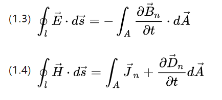
The above two equations describe the spin quantities of the field intensity, the integrals of the total electric field intensity and the total magnetic field intensity.
Corresponding to the rate of change of the magnetic flux and the rate of change of the potential shift (current intensity), respectively, for one turn along the path of the curve on a closed space curve.
The Gauss and Stokes formulas also allow the rewriting of the above four equations into differential form as follows.
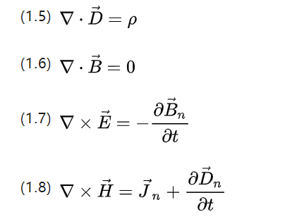
▽ for the Nabla operator, with vector dot product to calculate the scatter and fork product to calculate the spin, P for the charge body density, and Jn for the current density.
The above equations can describe basically all the electromagnetic behavior that occurs in all ac induction motor systems
1.2 Material polarization and magnetization for electrical energy
In an applied electric rotating magnetic field, the material molecules will change their orientation because the polarity is affected by the field strength.
The electric domains formed by the original unevenly arranged molecular groups of various sizes will be polarized because of the applied magnetic field, and the charge distribution orientation converges.
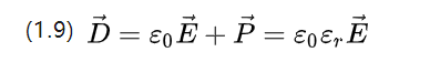
E0=8.854187817*10-12F/m is the vacuum permittivity, which is also the vacuum dielectric constant, and P is the relative dielectric constant, which is determined by the properties of the material itself.
(1.9) describes the potential shift density of the applied electric field and the corresponding polarization intensity picture together.
In an applied magnetic field, the corresponding magnetic domains and magnetization strengths can be obtained in the same way.
Unlike the electric field, a magnetic polarization strength M is introduced, which describes the difference between the magnetic induction strength of the material and that of the vacuum environment.
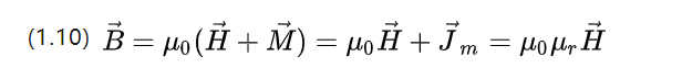
U0=4π*10-7 N.A-2 is the vacuum permeability and Ur is the relative permeability, which describes the ability of the material to allow a magnetic field to pass through.
If Ur<=1 is antimagnetic, the material prevents the passage of a magnetic field; if the image is paramagnetic, the material complies with the passage of a magnetic field.
If Ur>=1o 5 is ferromagnetic, the material such as ferro-cobalt nickel will enhance the magnetic field after magnetization. And then retain a certain strength of magnetic field after removing the magnetic field, which is called remanent magnetism.
In the process of motor operation there will be constant magnetization and demagnetization, so attention should also be paid to the examination of the hysteresis lines of different materials.
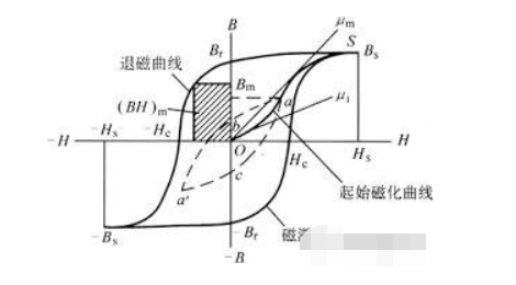
The hysteresis line describes the increasing magnetic induction of a magnetic material as the field strength increases under the action of an applied magnetic field of strength H.
This magnetic induction does not follow the field strength after reaching magnetic saturation.
After the magnetic saturation is reached, it is difficult to follow the increase in field strength. When the external magnetic field strength slowly decreases to zero, it can be seen that the demagnetization curve still retains the remanent magnetization B when it passes the zero point.
This remanent magnetization shows the general principle of manufacturing permanent magnets, i.e., directional magnetization followed by gradual demagnetization. When the inverse magnetic field is applied, the magnetic induction strength goes to zero or even increases in the opposite direction, and this excess is called the coercivity H.
1.3 Electromagnetic force and mechanical energy
The greatest value of the motor is to realize the conversion of electrical energy to mechanical energy, to do work externally and to execute the target motion.
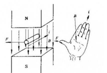
The motion of a charged particle in a magnetic field is subject to the Lorentz force perpendicular to the direction of motion, whose macroscopic expression is the Ampere force Hm = Il * B , which can be judged by using the left-hand rule to determine the direction,
I is the effective length of the conductor in the magnetic field in the direction of the current.
There is also a corresponding electric field force in the electrostatic field Fe=qE .
And both magnetic and electric fields are themselves fields, and the force applied to the charge or current element in them depends on the volume and field density, and thus the corresponding field force can be examined in terms of the field.
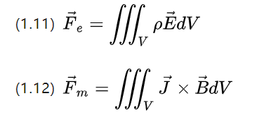
The above two equations still maintain the symmetry, the charge density P in a certain volume due to the electric field field field strength produces the electric force density fe = pE,
The current density J in a certain volume due to the magnetic field field strength produces the magnetic force density Fm = J * B (the above equation (1.12) must be used in the case of isotropic materials and constant current) .
This expression inspires us to directly examine the energy and energy density of the electromagnetic field.
In this way, the electromagnetic potential energy at a certain point can be determined by finding the gradient to obtain the corresponding electromagnetic force density and thus find the total electromagnetic force on the object under investigation.
1.4 Coil model
A coil is a fundamental element that forms a model of induction motors, bridging the circuit model of the ac motor and the physical model of the object.
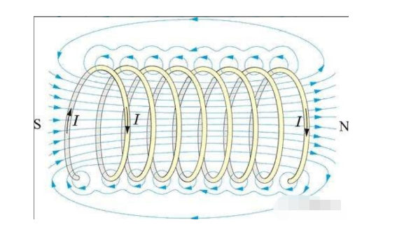
A straight section of energized conductor generates a toroidal magnetic field around it (according to equation 1.4).
When the conductor is closed at the beginning and end, the toroidal field forms magnetic lines of force in the center of the conductor ring that pass vertically through the conductor ring, such as a solenoid.
Considering only the current on the energized conductor, (1.4) simplifies to:
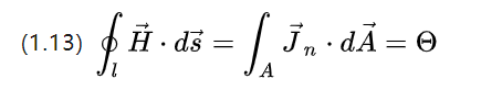
The magnetomotive force (magnetische Durchfluchtung), which is the source of the strength of the excitation field, is essentially the strength of the total current passing through a section of closed conductor in [A].
Since in practice the energized wire will be wound into a coil, the wire current is discretized and (1.13) is rewritten as
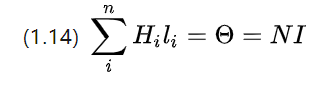
N is the total number of windings in the coil, i.e., the number of turns.
It can be seen that if the number of turns is higher, the total current is higher, the magnetic potential is higher, and the stronger the magnetic field can be excited.
A single-turn coil in a time-varying magnetic field will induce a voltage at both ends of the wire, a phenomenon described by (1.3).
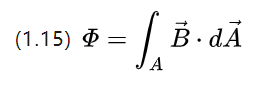
It can be understood that the magnetic induction can also be interpreted as the magnetic flux density, which can be obtained by substituting (1.3)
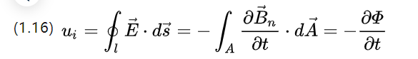
Ui is the induced electric potential, consider two forms of flux change, one is to change the coil area but change the flux density, then there are as follows;
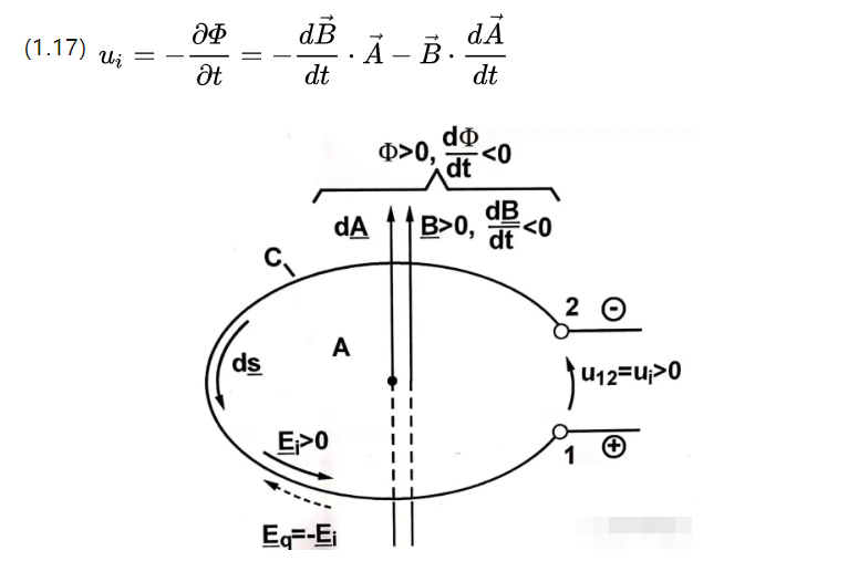
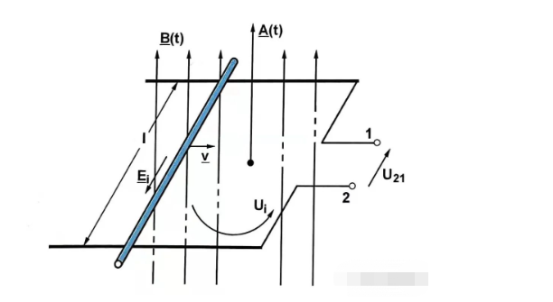
The former part is the formally transformed induction potential (transformatisch induzierte Spannung) and the latter part is the translationally transformed induction potential (translatorisch induzierte Spannung).
The former has a time-varying magnetic flux density, while the latter has a time-varying effective coil area.
This induction principle is mentioned in high school physics and is also known as the flute theorem.
When a coil has many turns, the total effective flux is exactly an integer multiple of the expanded coil turns, thus introducing the concept of a magnetic chain.
The chain is defined in the figure below.
Note that the magnetic chain is a scalar quantity, just like the magnetic flux. Since a change in current itself can also cause a change in flux, the tendency is to impede the flux change, which can be defined as:
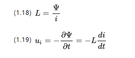
i is the varying current intensity, L is the self-inductance coefficient in Henry [H], and its size is related to the coil volume shape, number of turns, and magnetic permeability.
Coils in induction motors are made to have ferromagnetic material in the middle of the coil, such as an iron core, in order to increase the magnetic permeability, so that the coil is wound on the iron core, hence the name winding.
For a section of linearly homogeneous material, its self-inductance coefficient can be approximated by the following equation
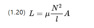
Self-inductance is a coil of its own current changes to induce the phenomenon of suppression voltage, its tendency to impede current changes about dc electric motor..
When two coils close to each other, in addition to their own self-inductance, but also because of the neighboring coils on the current changes and mutual inductance
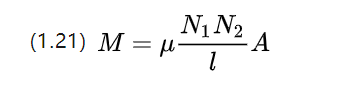
The coefficient of mutual inductance of materials with linear identities is approximated by the above equation, which shows that the mutual inductance is affected by the number of turns of the two coils at the same time.
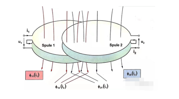
Ignoring the resistance and examining the self and mutual inductance of the two adjacent coils, the voltage equation can be listed from Figure 1.5 about dc motors
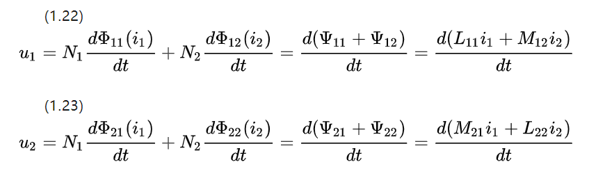
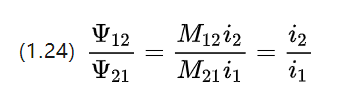
Since the coupling parts have the same material parameters and shape, the resulting mutual inductance coefficients are equal M12=M21.
So the size of the coupling chains on each coil is proportional to the current strength on the corresponding rotor windings coil for dc motor..
1.5 Ohm's theorem for electrical energy and magnetic circuits
In secondary school we studied Ohm's theorem, which states that the resistance of a conductor is the ratio of the voltage and current at both ends, and that there is a formula to describe the resistive material itself.
Q, which is the conductivity, which is exactly the reciprocal of the resistivity P and describes the ability to conduct current.
In addition to applying resistance, the relationship between voltage and current can also be described using the conductivity picture when the electric motor work.
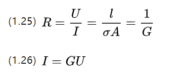
Now examine the current intensity per unit area, i.e., current density J = I/A e (e is the unit vector), with current density as a vector pointing in the direction of the current for ac motors.
This can be combined with the voltage equation U=E.l and (1.25) rewritten (1.26) as
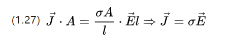
The above equation describes the Ohm's theorem at the microscopic level, i.e., the variation of the current density corresponding to a constant field strength applied to the conductor.
Lm is the effective length of the magnetic flux through a section of the magnetic circuit, and A is the corresponding flux area.
The above equation is very similar to the resistance formula.
Let us deform the magnetoresistance formula again and we can continue to obtain
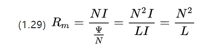
It can be seen that in units the magnetoresistance is actually the inverse of the inductance coefficient.
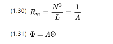
Continuing the analogy with the concept of conductance, we obtain the magnetic conductance A (magnetische Leitwert, in [H] or [Ωs])
In the circuit we find the differential elements for (1.26) and get the microscopic Ohm's theorem, so what is the microscopic Ohm's theorem corresponding to the magnetic circuit?
We can go on to rewrite equation (1.31), noting that the magnetic flux itself has a flux density B ,which then yields
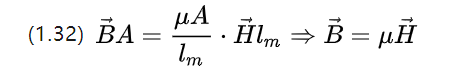
So the microscopic magnetic circuit Ohm's theorem is equation (1.10), and the magnetic field strength under is the flux density obtained from the magnetization of a constant magnetic field.
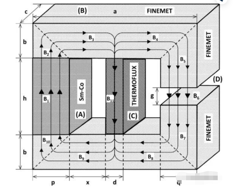
The computational analysis of the reluctance can be used to realize a micro-element analysis of the flux in the entire motor winding pole, core part and intermediate air gap part, which can realize a discrete finite element analysis FEM (Finite-Elemente-Methode) of the entire magnetic circuit.
It is also possible to apply Kirchhoff's theorem for the circuit in the magnetic circuit, which is very intuitive and convenient.
Welcome to share with us more information about electric motors in the comments area!
Any inquiry about electric motor, please contact the professional electric motor manufacturer in China as follows:

Dongchun motor has a wide range of electric motors that are used in various industries such as transportation, infrastructure, and construction.
Get a prompt reply.


