Skip to content
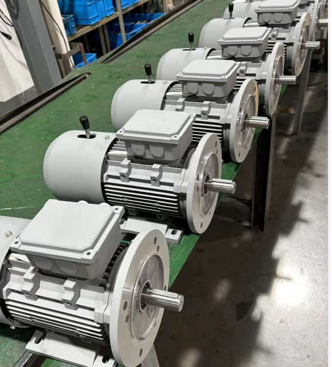
My friend sold two YEJ motors, the motor test without any abnormalities, including for the motor brake effect verification, but the fact that the motor could not be started when the user was using it. Service personnel arrived at the scene and found that there was a problem with the brake wiring, and the motor was all right after reconnection.
In response to the problem, in accordance with the advice of the service personnel, the factory wiring of this type of motor was improved, and similar problems did not occur again.
About the power loss brake
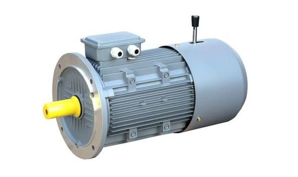
Electromagnetic brakes are additional devices commonly used in motors, and there are two types of energized brakes and de-energized brakes.
Electromagnetic brakes (hereinafter referred to as brakes) are widely used in machine tools, metallurgy, motors, chemicals, construction, packaging and printing, textiles, automated production lines and other mechanical transmission systems with positioning and braking requirements are commonly used. In addition to the advantages of easy control, fast braking speed, etc., the loss of power braking means that equipment can be safely braked in the event of an unexpected power failure, ensuring the safety of people and facilities.
Structural advantages and features
Compact structure Although the axial size of the power loss brake is small, the braking torque is large enough.
Rapid response The power failure brake uses a pop-up storage device to form the braking torque, and the pop-up arrow reset time is the braking response time.
● Long life time The new friction material used in the deactivated brake determines the high life time performance.
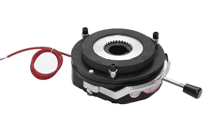
Working Principle of Braking
The electromagnetic brake is mainly composed of a magnetic choke with a coil, an armature, a coupling plate, a spring, a friction disc, a gear sleeve and other parts.
The magnetic choke is fixed on the machine base by the mounting screws, and the clearance is adjusted. To the specified value, the gear set is connected to the drive shaft through the key, and the outer teeth of the gear set are meshed with the inner teeth of the friction disk.
When the coil is disconnected, under the action of spring force, the friction disk and armature, seat (or coupling plate) friction, through the gear set will drive shaft braking, when the coil is energized, under the action of electromagnetic force, the armature is sucked to the magnetic choke, so that the friction disk release, lifting the brake.
Working conditions of the brake
● The relative humidity of the surrounding air is not greater than 85% (20±5℃)
● The surrounding medium is free of gases and dusts sufficient to corrode the metal and destroy the insulation.
● Class B insulation is used around the brake, and the voltage fluctuation does not exceed +5% and -15% of the rated voltage, and its working mode is continuous working system installation control requirements.
● The installation should ensure the accuracy of the fit between the drive shaft part and the brake.
● The brake must be cleaned before installation, and there must be no oil or dust on the friction surface or inside the brake.
● The gear sleeve must be fixed axially.
Simple calculation principle for model selection
The selection of the brake model depends to a large extent on the size of the required braking torque. In addition, factors such as the braking moment of inertia, relative speed, braking time, and operating frequency should also be considered. The following are the modeling rules recommended by a brake manufacturer. Different manufacturers may have some slight differences, but the principles are similar.
Calculate the required braking torque: T=K×9550×P/n
Where: T - required braking torque (N.m)
        P - transmission power (kW)

        n - brake braking relative speed (r / min)

        K safety factor (take K>2)
Brake maintenance and servicing
● After the brake is used for a period of time, due to the wear of the friction parts, it is necessary to readjust the clearance value by adjusting the screws, nuts, adjusting sleeves, etc. to make it conform to the specified value.
● The friction surface should always be kept clean and free from impurities.
Issues that must be noted during installation
If the brake and motor share the same power supply, ensure that the motor and brake are powered and de-energized at the same time.
● In view of the characteristics of simultaneous power supply and loss of power, ensure that the rated voltage of both is consistent.
The brake can be de-energized and the brake control released only at the rated voltage. If the voltage is lower, the motor cannot be started and the motor will be burned up; therefore, the motor with the brake installed must be started at full voltage.
For the short-circuit test of the motor, due to the low voltage applied (such as 380V three-phase asynchronous motor, the applied voltage is generally 100V), there is no need to block the rotation to meet the static state requirements of the motor.
The clearance of the brake disc is generally adjusted at the factory. After the brake is installed, the clearance should be approved and the compliance should be determined by inspection test.
The brake wiring should be reliable, and its terminal should be installed under the motor's own wiring fixing nut together with the motor stator terminal to ensure that the customer's wiring will not affect the reliability of the original wiring. This is the fact that we have talked about the measures to improve the brake wiring at the beginning of the article, which is also considered to mend the situation.
Analysis of the causes of failure
● The brake cannot be released after power is applied: Possible causes include damaged coil; power is not connected or insufficient voltage; the working gap is too large to be absorbed.
● Brake braking torque is not enough: motor speed is too high; motor load is too large; impurities or damage on the friction surface; insufficient spring force or failure.
● Brake is hot: Friction pad is slipping due to overload; insufficient supply voltage.
Get more information about brake motor , please contact with professional electric motor manufacturer - Dongchun motor China