 Skip to content
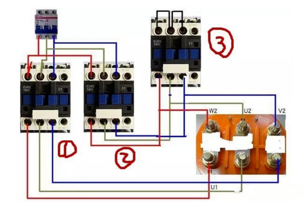
A star-delta buck start requires three contactors, a main circuit contactor, a star start contactor and a triangle run contactor.
It is best to use a time relay to control the time delay, and the main circuit contactor should be heated with an overload relay to protect the motor.
The star-delta step-down starter is only suitable for electric motors that are normally run in a triangular configuration.
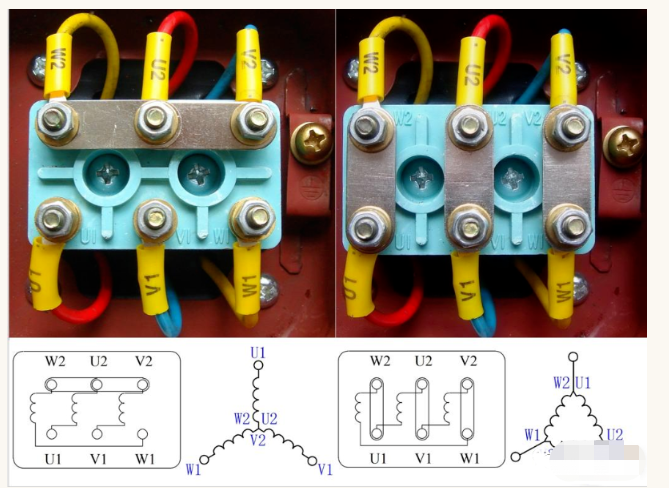
First we look at the internal windings of the induction motor.
There are three internal motor windings in a three-phase asynchronous motor, with both star and triangular connections.
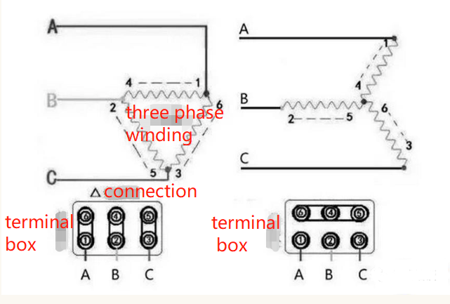
A star is where the three windings are joined together at the end, a triangle is where the three windings are joined at the beginning and end.
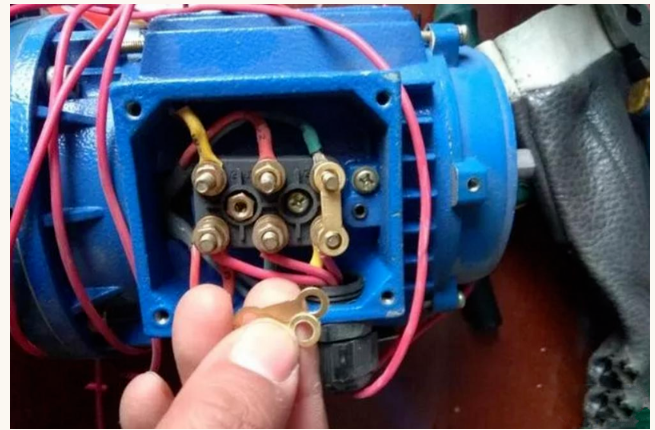
Remove these three connecting pieces when wiring.
Pay attention to the wiring of the mains section, it is best to use yellow, green and red wires.
From the above diagram we can see that at first the No.1 contactor and No.3 contactor are sucked together at the same time, as the upper end of the three contactors are shorted together, the three points are connected as one point, this one point is connected to the motor's W2,U2,V2, which happens to be a star connection, this point is called the neutral point.
Star start reduces the voltage and current, so the induction motor starts easily.
Once started, contactor 3 is disconnected, contactor 2 is activated and contactor 1 is the mains contactor, which remains activated.
After the No. 1 and No. 2 contactors have been activated, the three windings of the motor connected become a triangular connection and the induction motor can run normally at full voltage.
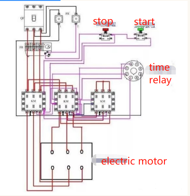
Here we see the complete wiring.
This is the complete wiring.
The thermal overload relay is connected to the mains contactor with the same phase sequence in all three phases.
The yellow, green and red diagram above shows the main line section and the black line is the secondary control line section.
Electric Motors doing star-delta starting have two important characteristics:
the star starting current and starting torque both become one third of the rated current.
The thermal overload relay is connected to the mains contactor with the same phase sequence in all three phases.
The above diagram shows the yellow-green-red main line section and the black line is the secondary line control line section.
A motor with a star-delta start has two important characteristics: the star start current and the start torque both become one third of the rated current.
It can be seen that the current at start-up is very small.
Star-delta starting is therefore suitable for applications where the starting torque of the motor is not strictly required, but where the starting current should be limited.
If the load is too heavy at start-up, it may not be able to carry the motor as the starting torque drops to one third of the rated torque, so generally a star-delta start is used when the load is light at start-up and heavy at run-up. If the motor starting current is too high, it will cause voltage fluctuations in the grid, in this case also use star-delta starting.
Note the wiring of the time relay in the following diagram.
Therefore, star-delta starter is suitable for conditions where the starting torque of the motor is not strictly required but the starting current should be limited.
Therefore, it is not possible to generalise the size of the motor power to determine whether to use star-delta starting. If the load is too heavy when starting, it may not be able to carry the motor because the starting torque drops to one third of the rated torque, and generally star-delta starting is used when the load is light when starting and heavy when running. If the motor starting current is too high, it will cause fluctuations in the grid voltage, in this case also use star-delta starting.
Pay attention to the wiring of the time relay, which is very simply described.
To clarify these issues, we first need to review some basic electrical theory.
Look at the diagram below and let's start by understanding the relationship between phase voltage and line voltage, phase current and phase current for three-phase load circuits in different connection methods.
We know from the diagram that if we take the current three-phase four-wire low-voltage (TN) power supply system (the so-called utility) used in large numbers in China, when the load remains unchanged, the phase voltage added to both ends of the load when the star connection is one third of the root of the line voltage; and the phase voltage added to both ends of the load when the angle connection is equal to the line voltage.
For the same load, the phase current flowing through the load is equal to the line current when connected in star mode, while the phase current flowing through the load is one-third of the root of the line current when connected in angle mode (be careful to understand the difference between the expression here and the expression in the diagram below, don't get confused because the two mean the same thing, only the expression is different).
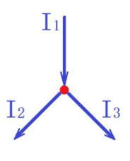
Next, let's review Kirchhoff's nodal current law, see the diagram below. From the diagram we know that the current flowing through any node is always constant equal to the current flowing out of that node [it can also be said that the algebraic sum of the currents in each branch circuit (AC is a vector sum) is equal to zero], that is, the current does not accumulate in the node
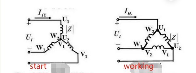
Let's take a look at the common star and angle connections of the internal windings of a three-phase squirrel-cage asynchronous motor, see the diagram below.
This is the standard connection, one of the basic knowledge that a qualified electrician must master. After understanding their principles, we can flexibly apply and maintain our equipment in future production practice, so that the equipment can serve the production better.
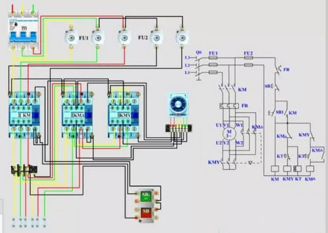
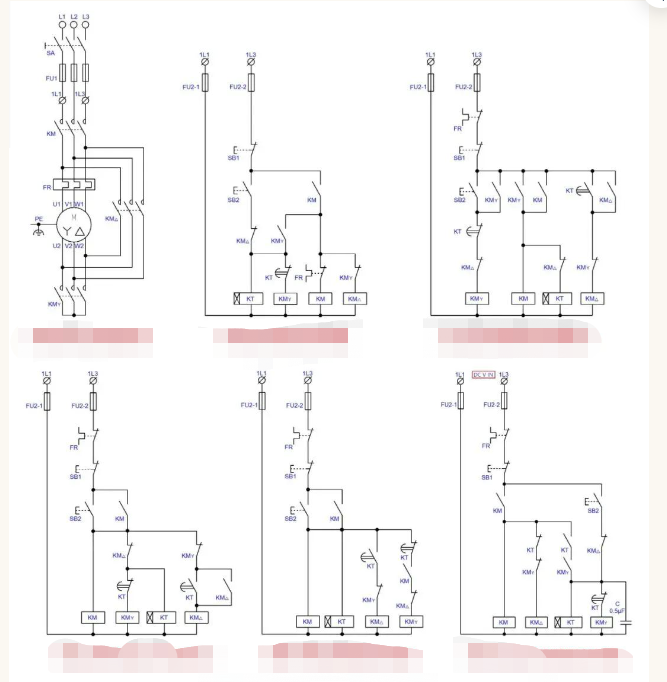
The next step is to start the analysis of the star/delta step-down starter circuit, see the diagram below.
The first main control circuit on the left in the diagram is the standard star/delta buck start main control circuit, which is a general purpose circuit.
The first of the auxiliary control circuits on the left and the lower side is the traditional standard generic auxiliary control circuit; the second and third are one of the auxiliary control circuits now circulating in society; the fourth is the auxiliary control circuit after I have standardised the circuit; and the fifth is the auxiliary control circuit after I have standardised it.
Note: The so-called standardization is to re-draw according to the relevant standard provisions, not completely and thoroughly according to the standard requirements, so that the workload is too large, and for the discussion will not be necessary, as long as everyone can understand it, please understand.
Let's first look at the standard star/delta step-down main control circuit, which constitutes a star step-down start when the KMY is closed. Based on the theoretical discussion of the relationship between phase voltage, line voltage, phase current, line current and the nodal current law started earlier, we know that the star point formed by the KMY (which can be referred to as the zero or neutral point) will have current flowing through the main contacts of the KMY into the star point formed by the wire, and that the current flowing into the star point is equal to the line current.
As the load in a triangular connection (in this case the three-phase winding of the motor), the voltage applied to the ends of each phase of the load is the line voltage (i.e. 380V), i.e. the phase voltage is equal to the line voltage.
When we change to a star connection (the load and input voltage remain unchanged), the voltage at both ends of each phase of the load is one third of the root of the original voltage (i.e. 220V), then the current flowing through each phase of the load is only 1/3 of the original (angular connection) current, which is the principle of voltage reduction starting.
As the phase current of the star connection is equal to the line current, this means that the current flowing through the main contacts of the KM (main contactor) is the same as the current flowing through the main contacts of the KMY (closed star contactor). Therefore, whether or not synchronously closed or broken, the arc generated by the two contactor main contacts are the same, there is no synchronous closure of the two when the arc will be larger than the arc generated when not synchronous closure of the argument.
Therefore, as long as the correct choice (selection) and the use of qualified contactor, under normal circumstances will not appear when the contactor action due to arcing caused by contact serious ablation or adhesion of the possibility.
However, in production practice, the usual design is that KMY closes before KM. The purpose of this is to extend the service life of KMY contacts and reduce operating costs. The principle is that the KM is selected according to the angular operating current, while the KMY is selected according to the star connection current. If the KMY closes before the KM, there will be no start-up arcing (there will still be when the star/angle switch is broken), so that the arcing at start-up is borne by the KM with higher specifications than the KMY, which is much better than the KMY with lower specifications.
If the design of KMY in the star/angle switch first disconnect KM and then disconnect KMY best (because the arc when breaking than when closed much larger arc), but this will cause the auxiliary control circuit structure complexity and economic cost increases, sometimes more than worth the loss.
Look again at the KM△ angular connection contactor. As the angle connection when the current flowing through the KM△ main contact is the phase current, equal to the root of the line current 3 parts, generally speaking, in order to be safe and reliable, is selected according to the line current.
This is because the arc may be larger during the conversion process and may easily burn the contactor contacts. Of course, if KM△ is closed before KM, KM△ can be selected according to the phase current (one third of the root number of the line current).
But this will make the control circuit structure complex, equipment manufacturing costs not only did not come down, it is not good enough to make more losses than gains.
The analysis of the main circuit of the star/delta buck start summary: as long as the correct choice of the type of contactor specifications and qualified products, under normal circumstances contactor contact ablation should not be a problem, that KM and KMY synchronous action will cause arcing is a misunderstanding.
In reality, there are many reasons for arcing, but the main one is that the star/angle conversion time is not set properly, or the load is too heavy.
The start time is not enough to convert too early; some are the quality of the motor itself or the usual maintenance is not enough, the running current becomes large; some are the motor running with disease or unreasonable design resulting in long-term overload operation of the motor caused, of course, does not exclude the design or The type, specification and quality of the contactor used in the maintenance process do not meet the requirements.
In addition, please note that star/delta voltage reduction starts have a certain range of application, and are not necessarily better than other voltage reduction starting methods. Because the starting current of star/delta voltage reduction is 1/3 of the full voltage starting current, the starting torque is only 1/3 of the original starting torque, which is only applicable to light or no-load starting equipment (equipment such as pumps or air compressors must close the inlet/outlet valve or empty the compressed air tank before starting the star/delta voltage reduction starter motor).
For heavily loaded starting equipment, starting times of more than 30 seconds (especially more than 1 minute) have a significant impact on the motor and the supply line (especially if the supply transformer is under capacity).
Therefore, the heavier the load (or the higher the power) the motor, the other starting methods [e.g. autotransfer buck start, extended side triangle buck start, stator series reactor (or resistance) buck start, soft starter buck start, frequency converter inverter start, etc.] should be used to select the starting method according to the specific actual situation.
Therefore, it is a misconception to think that star/delta buck starting is much better than other buck starting methods;
It is also a mistake to think that no matter what equipment is used, as long as buck starting is used, all star/delta buck starting methods are used (the advantage of star/delta buck starting is its simple structure and small size).
The following is a discussion of the auxiliary control circuit for star/delta buck starting.
The auxiliary control circuit, referred to as the control circuit, is a circuit that controls the object being controlled according to the process requirements. Of the five control methods shown above, the control methods are much the same except for the fourth, which differs only in circuit construction, the fourth being the opposite of the first three, and the last being the addition of an angular changeover contactor delay function to the first three control circuits.
The first control circuit is the traditional, standard control circuit, which is first sealed star (KMY) before the main contactor (KM) closes to supply the main circuit with a buck start, and after the start is complete turns to angular operation and the time relay exits operation.
This circuit has a simple circuit structure yet meets the characteristics of safe and reliable operation.
The second and third control circuits are similar to the first control circuit in that they both seal the star first before supplying a step-down start, and the time relay exits after the start is complete.
The difference is that the circuit structure is a little more complex, adding some double chain contacts, with more safety and reliability than the first control circuit.
In particular, the second control circuit, the contacts used the most, although the safety and reliability increased a lot, but also a lot more difficult to maintain.
The fourth is a designed circuit. For this circuit, I personally think that it is not very reasonable and perfect.
Although the double chain function is added, the main contactor KM closes before the sealing star contactor KMY, and the sealing star contactor KMY often operates under arcing, which is always better than sealing the star first and then energising the buck start.
Although harmless, but compared to the first seal star, after the seal star so that the contactor KMY contacts are always much shorter than the first seal star contact life (more than double the work with arc light).
The long-term involvement of the time relay KT in operation is a hard part of this circuit.
As we know, the life of a component that is constantly energised and involved in operation is much shorter than if it is not, and the power consumption increases.
As the saying goes, "more incense burners, more ghosts", your time relay KT is involved in long-term operation, so it may give you a failure in operation at some point, affecting the efficiency of the equipment and increasing operating and maintenance costs.
The fifth is the circuit provided.
Although in the operation of the action and the previous three similar, with the first sealed star after the power and time relay is not involved in the operation of the function, but the use of parallel capacitor C to extend the angle contactor KM△ closure is a bit of a snake - redundant.
And the delay function only in the DC supply control circuit to play a role in the AC circuit, but no role, or even a redundant and cumbersome thing.
You don't know when to give you a breakdown or leakage caused by a fault.
Be aware that the reverse peak voltage of an inductor in a DC circuit is four to five times more than the rated voltage.
Well, that's it for the analysis of star/delta buck starting circuits.
Welcome to leave a message in the comments area for any information.
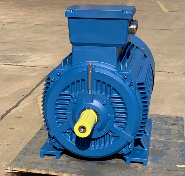
Any inquiry about electric motor, please contact the professional electric motor manufacturer in China as follows:

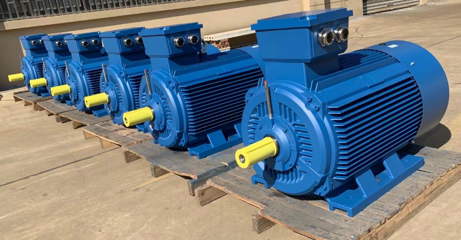
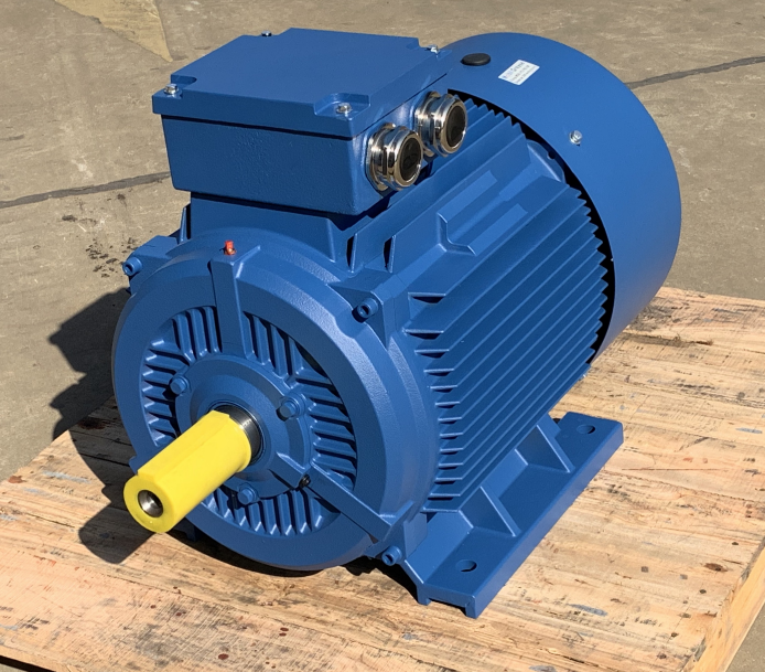
Dongchun motor has a wide range of electric motors that are used in various industries such as transportation, infrastructure, and construction.
Get a prompt reply.


