 Skip to content
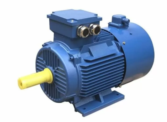
1 Characteristics of inverter motor
1.1 Electromagnetic design
For ordinary asynchronous motors, the main performance parameters considered in the design of inverter motors are overload capacity, starting performance, efficiency and power factor.
As for the inverter motor, since the critical turndown rate is inversely proportional to the power supply frequency, it can start directly when the critical turndown rate is close to 1.
Therefore, the overload capacity and starting performance do not need too much consideration, but the key problem to be solved is how to improve the motor's adaptability to non-sinusoidal power supply.
First, reduce the stator and rotor resistance as much as possible.
By reducing the stator resistance, the fundamental copper consumption can be reduced to compensate for the increase in copper consumption caused by higher harmonics [3].
Second, to suppress the high harmonics in the current, the motor inductance needs to be increased appropriately.
However, the rotor slot leakage resistance is larger, and its skin effect is also larger, and the high harmonic copper consumption increases.
Therefore, the size of motor leakage resistance should take into account the reasonableness of impedance matching in the whole speed regulation range.
In addition, the main magnetic circuit of inverter motor is generally designed to be unsaturated, one is to consider that the high harmonics will deepen the magnetic circuit saturation.
The other is to consider that the output voltage of inverter will be increased appropriately at low frequency in order to improve the output torque.
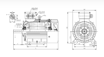
1.2 Structure design
Structure design, mainly also consider the non-sinusoidal power characteristics of the inverter motor insulation structure, vibration, noise cooling mode, etc.
First of all, in the insulation level, generally F grade or higher, strengthen the insulation to ground and line turn insulation strength, especially to consider the ability of insulation to withstand shock voltage.
For the vibration and noise of the motor, we should fully consider the rigidity of the motor components and the whole, and try our best to improve its inherent frequency to avoid the resonance phenomenon with each force wave.
Generally, forced ventilation cooling is used, i.e., the main motor cooling fan is driven by an independent motor [4].
Bearing insulation measures should be adopted for motors with capacity over 160 KW, mainly because it is easy to produce magnetic circuit asymmetry, which also generates shaft current, and when the currents generated by other high-frequency components act together.
The shaft current will be greatly increased, thus leading to bearing damage, so insulation measures are generally adopted.
In addition, for constant power inverter motor, when the speed exceeds 3000/min, special grease with high temperature resistance should be used to compensate for the temperature rise of the bearing.
2 Frequency conversion motor common fault diagnosis,corroded battery terminal
2.1 Turn-to-turn short circuit and partial discharge,blown fuse
Turn-to-turn short circuit and partial discharge are the more common forms of the current inverter motor insulation type fault, in which turn-to-turn short circuit is generally manifested as a large area of damage to one of the motor coils.
Partial discharge is concentrated in the motor coil appearance is good, but the insulation resistance has been shown to zero state.
At this time, the motor insulation system is affected by the damage, not just a single factor, but local discharge, local media heating and other factors.
Local discharge: At present, in the operation of small and medium capacity inverter, it is common to choose to use IGBT power device pulse width modulation technology.
The components mutually constitute the PWM speed control device can provide towering spikes, the wave has a steep front characteristics, while its modulation frequency is high, so the impact of the harm brought to the insulation is more serious.
Local dielectric heating:
If the electric field strength E in the motor has significantly exceeded the insulation critical value, then the degree of loss of the dielectric will also become more and more serious.
Especially in the situation of rising frequency, the partial discharge will also increase, and then generate heat, which will inevitably bring more serious leakage current and other problems [1].
Over time, it will not only lead to an increase in the loss per unit volume, but also the temperature rise of the motor will continue to rise, invariably leading to faster and faster insulation aging.
Cyclic alternating stress:
the PWM inverter power supply method, the inverter motor can be directly braked in various ways provided by the inverter when it is put into formal use.
The motor insulation will age faster and faster throughout its insulation under the influence of cyclic alternating stress.
Because the design link in the early stage does not take into account the electrical and mechanical integrity, so the aging process of the motor speed will continue to increase.
2.2 Bearing damage, excessive vibration
Combined with the effect of PWM inverter drive system when put into formal operation, the bearing damage problem of the whole inverter motor will become more and more serious, and even often there will be bearing damage, excessive vibration and other problems.
A 690kW inverter motor in a high-speed wire rod plant has started to have serious vibration and other problems in just 3 months after being put into operation.
For the problem of troubleshooting and maintenance, the motor was disassembled off-line and it was found that the surface of the bearings had more burning spots, while these burning spots were also more obvious, and the reason for this was that the motor bearings were seriously damaged due to the impact of the shaft current owing to the high inertia loads.
2.3 Current oscillation about the battery terminals
Combined with the example of the analysis, a cold rolling mill within the existing 250kW/400V/430A inverter motor system in operation, has been continuously burning device failure problems in the motor overload.
When the inverter was overhauled, a V/F control no-load test was conducted on the VFD motor in advance, and according to the test results.
It was found that the electric motor showed abnormal current in the range of 7 to 30 Hz, and more importantly, the amplitude of the three-phase current had obvious oscillations, with the highest oscillation current amplitude reaching 700 A.
After the fault problem appeared, the relevant overhaulers immediately targeted the existing According to the test results, it was found that the electrical motors and inverters in the same frequency range were unstable and other problems [2].
Near the working frequency, the electric motor state is more stable, but if the frequency at 40Hz, especially in the range of 20 to 30Hz, the electric motor current will oscillate with a cycle of about 10 to 20Hz, and if the peak performance at this time is too high for excess heat, then the whole operating state of the electric motor will be seriously affected.
To analyze the situation, for the asynchronous motor, if it is in the state of zero rate of difference, then its transient positive and negative torque changes will have unstable factors.
More importantly, the torque pulsation under the inverter drive and the transient change of V/F will cause more obvious torque fluctuation, which may become vibration and even continuous vibration.
There is a certain correlation between the torque pulsation and harmonic current and other factors in this situation.
If the inverter motor is operating in an unstable state, it is important not to simply think that there is a fault problem with the motor or inverter, but to conduct a comprehensive analysis of both according to the parameters of the electric motor as well as the inverter, so that a reasonable judgment of the fault can be made for the modern drives.
3 inverter motor fault maintenance measures
The application of inverter motor is becoming more and more widespread, for inverter motor repair, need to take effective measures for the characteristics of inverter motor, in order to ensure the normal power quality operation of the inverter motor.
3.1 Frequency conversion motor maintenance requirements
VFD motors i.e frequency variable drive motors are generally selected 4-stage motor, the base frequency operating point is designed at 50Hz, frequency 0-50Hz (speed 0-1480r/min) range of motor for constant torque operation, frequency 50-100Hz (speed 1480-2800r/min) range of electrical motor for constant power operation.
The entire speed range (0-2800r/min), basically meet the General drive output equipment requirements, its working characteristics and DC speed control motor, smooth and stable speed regulation.
If the constant torque speed range to increase the output torque and input power, you can also choose a 6-stage or 8-stage motor, but the size of the electric motor is relatively larger [5].
Since the electromagnetic design of the frequency-controlled motor uses flexible CAD design software, the design point of the power source motor's fundamental frequency can be adjusted at any time.
We can accurately simulate the major cause for motor's operating characteristics at each fundamental frequency point on the computer, thus also expanding the motor's constant-torque speed range, and according to the actual working conditions of the electric motor.
We can make the motor's power larger within the same seat number, and also on the output torque of the electric motor can be increased on the basis of the same inverter to meet the design and manufacture of the electric motor in the best condition under various working conditions with the equipment.
Frequency variable drive motors can be equipped with additional speed encoders to achieve the advantages of high precision speed and position control and fast dynamic response.
The electric motor can also be equipped with a special DC (or AC) brake to achieve fast, effective, safe and reliable braking performance.
Due to the adjustable design of frequency-controlled motors, we can also manufacture a variety of high-speed motors to maintain the characteristics of constant torque at high speeds, replacing the original medium-frequency motors to a certain extent, and at low prices.
Frequency variable drive motor for three phase AC synchronous or asynchronous motor, according to the inverter output power supply has three phase 380V or three phase 220V.
So the motor power supply also has three phase 380V or three phase 220V different differences, generally below 4KW inverter only three phase 220V.
Because the frequency variable drive motor is to be given drive base frequency point (or inflection point) to divide the different constant power speed regulation area and constant torque speed regulation area of the inverter.
So the inverter base frequency point and the inverter motor base frequency point settings are very important.
3.2 Improve insulation performance
Through the reasonable use of corona-resistant enameled wire, it is beneficial to properly increase the screen varnish layer.
Through the application of quantum chemical technology, the chemical materials used for shielding can be directly involved in the condensation reaction of the varnish-based polymer as the main material of the varnish to ensure that the high-frequency impulse-resistant voltage can be promptly dispersed as well as the dissolution process, so as to improve the entire corona resistance of the varnish.
The tank insulation material is made from several different mixtures such as NHN and F-grade DMD, which are not corona-resistant because of their strong organic characteristics. Based on this, a new type of slot insulation containing mica is chosen to be used.
The addition of mica helps to improve corona resistance.
In terms of interphase insulation, the type of product with polyester fleece on the surface should be chosen.
This type of product has obvious advantageous characteristics in terms of resin absorption compared to other materials and is conducive to the formation of an effective bond with the wire.
The impregnation process has always been one of the most important processes in the overhaul of inverter motors, and the most important point is to avoid the flow of resin and loose connection.
Usually choose to use VPI to treat, or after VPI treatment, can be appropriate to increase the impregnation process, which is conducive to the timely elimination of air bubbles, and constantly fill the air gap in the winding, but also to improve the electrical and mechanical strength of the winding, to ensure that its own heat and dirt resistance to be strengthened.
If conditions allow, the treatment can be carried out by UV heating and current drying method, which can achieve good results.
In addition, it should be noted that in the whole process of inverter motor overhaul, avoid causing short circuit and other problems, to ensure that the motor bearings and other parts of the assembly can meet the basic precision requirements, try to avoid serious local heating and other problems caused by eddy current loss, otherwise it is bound to affect the insulation performance of the motor.
3.3 Eliminate the impact of shaft current
To ensure that the shaft current can be reduced to a harmless level, it is usually necessary to ensure that the shaft current is controlled at 0.4A/mm2 or 0.35mV or less.
Based on this, targeted countermeasures should be taken to eliminate the adverse effects of shaft current, taking into account the specific environment and type of motor use.
Suppression of power supply harmonics:
To eliminate the impact of shaft current, through the reasonable application of the inverter power supply speed control system, you can directly add a filter in it, or use the supporting frequency conversion speed control device, which is conducive to reducing harmonics, but also reduce the shaft current and vibration and other adverse effects.
Bearing insulation measures:
take targeted insulation measures to deal with the bearings, but also in time to eliminate the adverse effects of shaft current. The current common method is through the motor load side bearing grounding, non-load side bearing insulation and other means, the use of rolling bearing structure.
You can choose to insulate the bearing as one of the main bearing form, or in the bearing inner ring, outer ring surface and other parts, the use of ion spraying method uniform spray 50 to 100mm of insulation layer.
In addition, depending on the actual situation, it is also possible to add a sleeve directly to the end cover bearing chamber, add an insulating layer between the sleeve and the end cover, and do a good job of fastening the inner and outer cover bearings.
When using the sliding bearing structure, you can directly increase the pad epoxy glass cloth plate at the fixed bearing position, or at the position of the inlet and outlet oil pipeline, add insulation pipe joints, etc., using these methods can effectively eliminate the adverse effects of shaft current.
In addition to the above methods, we can also choose to use strategies such as monitoring lines to strengthen insulation and improving the motor operating environment to eliminate shaft currents.
In a word, no matter choose to use any method, according to the characteristics and requirements of the actual situation, from a number of perspectives, in order to achieve good results.
3.4 Improve the current oscillation problem
After long-term tests, summaries and analyses, in order to ensure the effective treatment of the current oscillation problem and improve the current instability at the same time.
This can be achieved by continuously increasing the motor rotational inertia or carrying the load, or also by appropriately increasing the DC-side capacity of the voltage inverter, which is conducive to reducing the impact of voltage fluctuations. In combination with the current state of PWM control inverter operation.
The use of fast switching components or direct reduction of the PWM modulation frequency will help to avoid fluctuations in the output voltage affected by the dead zone.
In order to improve the current oscillation problem, you can also use the motor with a high turndown rate, using current feedback, etc., can ensure that the circuit vector control situation, such as timely feedback, in order to ensure the improvement of the stability of inverter motor operation.
Welcome to share with us more information about electric motors in the comments area!
Any inquiry about electric motor, please contact the professional electric motor manufacturer in China as follows:
Dongchun motor has a wide range of electric motors that are used in various industries such as transportation, infrastructure, and construction.
Get a prompt reply.


