 Skip to content
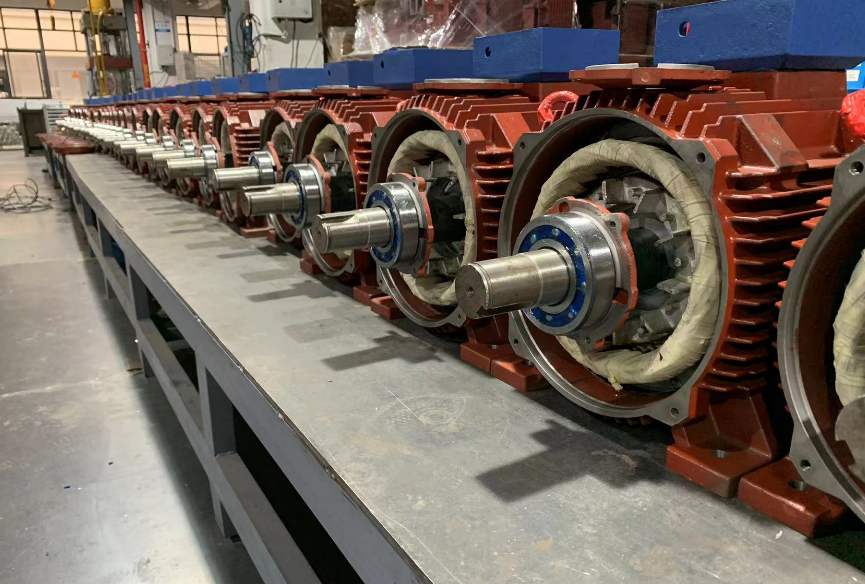
Stator assembly
Most of our electric motor factories produce small motors using the external press fitting process.
Stator core in the embedded line after dipping and baking, pressed into the seat must ensure that the axial position in line with the requirements of the drawings.
Otherwise it will make one end of the coil stretched too much, resulting in total assembly difficulties, and will make the electric motor air gap magnetic potential increases, affecting the performance of the electric motor.
It will also increase the wear of the axial force on the rotor of electric motors.
The axial position of the stator core in the housing is generally ensured in the press-fit tire tool.
The size of the pressure cap is controlled so that the position of the core after press-fitting is in accordance with the requirements of the drawing.
To ensure that the stator core does not rotate in the housing, the contact between the inner circle of the housing and the outer circle of the stator core alone is not sufficient, so each electric motor is also fitted with a stop screw to completely fix the core in the housing.
Rotor assembly
The assembly of the rotor of an asynchronous motor includes the assembly of the rotor core and shaft, the assembly of the bearings and the assembly of the fan.
It is the key component of the electric motor production.
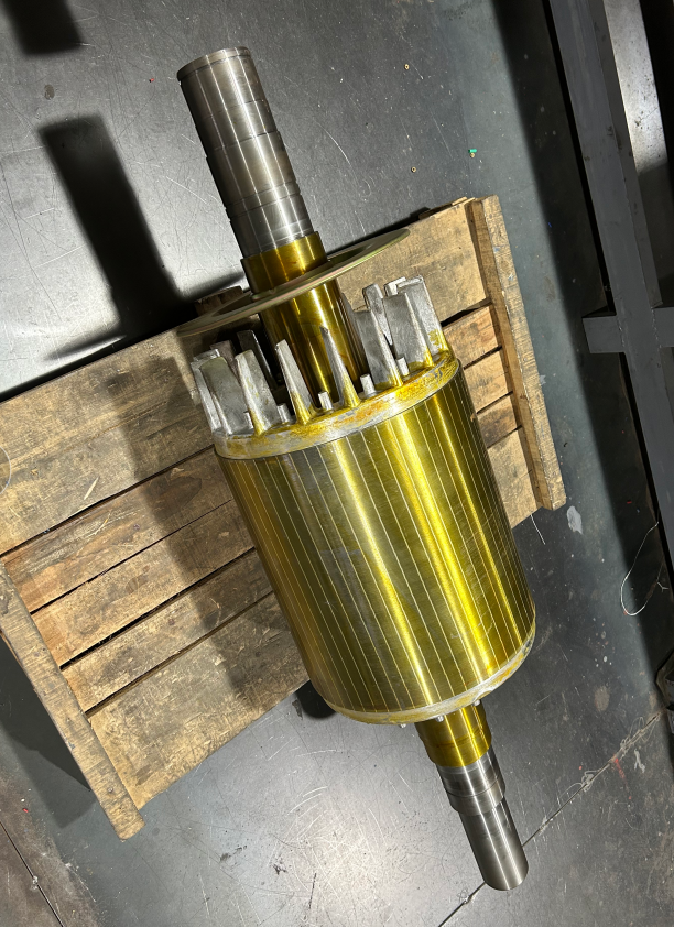
Assembly of the rotor core and shaft
When the electric motor is in operation, mechanical power is output through the rotor shaft, therefore, the reliability of the combination of rotor core and shaft is very important.
When the rotor outer diameter is less than 300mm, the rotor core is normally pressed directly onto the rotor shaft; when the rotor outer diameter is greater than 300mm to 400mm.
The rotor bracket is pressed into the core first, and then the rotor shaft is pressed into the rotor bracket.
The Y series electric motors adopts a structure where the rotor core is pressed directly onto the rotor shaft from most manufacturers
There are three basic forms of assembly between the rotor core and the shaft on the production line : knurled cold press fit, hot sleeve fit and key connection fit.
Knurling cold press fit In the knurling cold press fit, the shaft processing process is: finishing the core file a knurling a grinding, then pressed into the rotor core, and then finishing grinding shaft extension, bearing file and finishing the outer circle of the core.
When using the knurling process, excessive interference is also not permitted.
Because the size of the cold pressing pressure is proportional to the amount of interference, when the amount of interference is too large, it may not be pressed in, or the material may be deformed or damaged due to excessive internal stress.
Hot-sleeving is generally carried out by using the residual heat from the cast aluminium rotor (or by reheating the rotor).
The hot sleeve process saves cold pressing equipment, while the combination of rotor core and shaft is more reliable.
Because the hot sleeve is heated to expand the inclusion and then cooled, the hole of the inclusion shrinks to hold the inclusion, which ensures sufficient interference values and high reliability.
The advantage of the key connection is that it ensures the reliability of the connection and facilitates the organisation of flow production.
The disadvantage is that the processing process increases and the keyway in the shaft reduces the strength of the shaft, especially in small electric motors.
When using a key connection, the width of the key is selected according to the specified requirements.
In order to simplify the process, it is usually possible to use the same keyway width with the shaft extension for electric machines.
Bearing assembly
In small and medium-sized asynchronous motors, rolling bearing construction is widely used. They are lighter than plain bearings, require less frequent maintenance during operation and consume less lubricating oil and grease.
At the same time, rolling bearings have a small radial clearance and are more suitable for asynchronous motors with a small air gap.
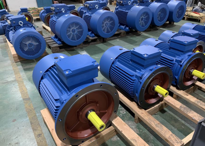
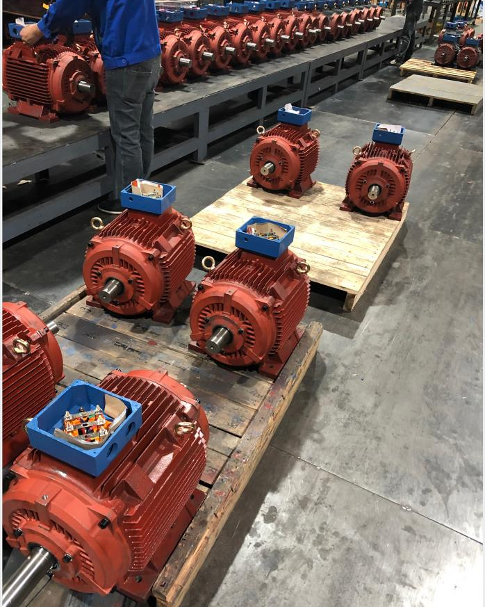
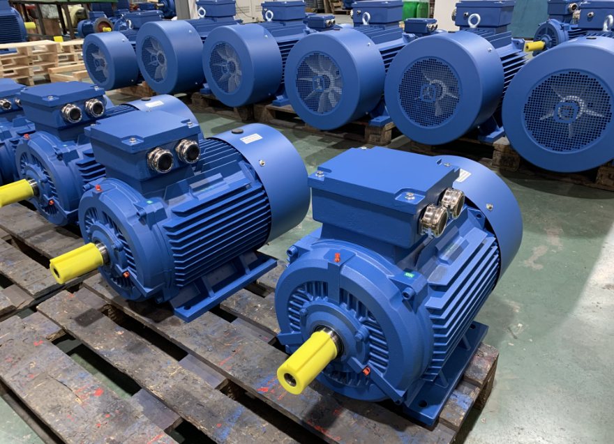
General assembly
The total assembly of small and medium-sized motors includes the rotor set into the stator, the installation of other components, such as end caps, junction boxes, external fans and brush devices, etc in many manufacturers.
After the total assembly, it is also necessary to carry out tests and the exterior finishing of the motor.
General assembly of rotor into stator for electric motor production
Sleeving the rotor into the stator is one of the key processes.
Improper operation can easily cause bruising of the windings and sometimes even deformation of the rotor shaft.
When inserting the rotor, it is necessary to pay attention to the corresponding position of the shaft extension and the junction box.
If the mass of the rotor is less than 35kg, it can be put into the stator by hand.
For larger rotors, lifting tools are required.
operating, first lift the tool at the lifting ring 2 and set it on the rotor shaft, then lift the rotor at the lifting ring 1 instead and hold the lever 3 to make the rotor penetrate into the stator horizontally and smoothly.
Installation of end cover
When installing the end cap, generally install the non-axle extension end first.
Apply a thin layer of oil on the assembly stop surface to prevent the mouth part from rusting.
After installing the end cap, tap around the end cap to tighten the end face of the end cap and the seat, and then tighten the bolts diagonally in turn.
When the second end cover is installed, the rotor needs to be lifted flat (small motor can not be lifted), then the end cover stop knocked together, tighten the bolt.
If the two end caps are installed with different axes, or the end surfaces are not parallel, the rotor may rotate stagnant, you need to use a hammer to knock around the end caps to eliminate the different axes, not parallel phenomenon, so that the rotor rotates flexibly.
Then install the outer bearing cover, tighten the bearing cover screws.
Air gap adjustment
For the whole round end cover rolling bearing of medium-sized motor, when the rotor is inserted into the stator, the end cover of the ball bearing end should be installed first, and then the end cover of the roller bearing end should be installed to prevent the rolling bearing from being damaged.
When the end cover of the ball bearing end must be installed first, the end cover screw should not be tightened, after the end cover of the ball end is installed, then tighten the screw.
After the end cover is installed, to adjust the air gap.
The method of adjustment is to use the jack (four at both ends) to adjust the relative position of the end cover.
Use the plug ruler in the mutual difference 120. position for measurement (both ends), until the air gap uniformity in line with the technical conditions of the standard.
After adjusting the air gap will be screw fastening, in the horizontal punching machine according to the location of the drawing drilling dumpling positioning pin hole, and play people positioning pin.
Assembly of brush system in power electronics
In the electric motor with slip ring contact (such as large and medium-sized winding rotor asynchronous motor).
The quality of brush assembly has a great impact on the situation of the conduction; in the motor with commutator, the commutation of the situation is good or bad, often closely related to the quality of the brush system assembly.
The brushes for collector ring and commutator are generally electrochemical graphite brushes and metal graphite brushes.
Electrochemical graphite brush is made of natural graphite after processing to remove impurities and then sintered.
According to the different ratios of raw materials, it can be divided into graphite-based, coke-based and carbon-black-based.
Carbon black-based brushes have higher resistance coefficient and contact voltage drop, and are suitable for motors with difficult commutation; graphite-based brushes are commonly used in normal motors.
Electroplated graphite brushes have less hardness and slower wear, current density is generally available at 10-12A1cm2. metal graphite brushes are suitable for low voltage, high current motors, it is sintered by adding 40% -50% copper powder in graphite.
It has high density, low hardness, low wear coefficient, low resistance coefficient, low contact pressure drop, slow wear, and current density is generally available at 17-20A/cm2 for higher quality .
Brush arrangement in the DC motor, because in the positive and negative brushes under the commutator wear degree is inconsistent, so must be reasonable arrangement of the brush arrangement position.
The brushes should be staggered on the commutator surface.
Automation of small motor assembly for electric power trains
In order to improve labor productivity, reduce production costs, shorten the product development or production cycle, in order to enhance the market competitiveness of products. The motor industry at home and abroad are competing to introduce automation technology in the field of motor assembly.
The early motor assembly automation system, represented by the motor semi-automatic assembly line, was used for the assembly of small motors with large quantities and few specifications.
This semi-automatic assembly line includes automatic assembly machinery such as rotor loading machine, bearing press fitting machine, end cap press fitting machine and screw tightening machine, whose functions are: stator loading, rotor insertion into the stator, bearing press fitting, end cap loading and butterfly and nail tightening.
The main assembly process is done by machinery, and the auxiliary work is done by hand.
The equipment of this semi-automatic assembly line is fixed and has a certain working tempo, and the working efficiency is high, which can reach 25-40s/set.
In order to meet the requirements of automatic assembly of multi-species and small-lot products, foreign countries have developed flexible assembly cells (FAC) and flexible assembly systems (FAS), both of which use computer-controlled robots as the core equipment and thus have a high level of automation.
The flexible assembly cell includes a handling robot and multiple assembly robots.
The handling robot is responsible for handling various parts and delivering the assembled parts to the workstation of the assembly robot in order, and then carrying the assembled parts to the conveyor belt to send them away.
Equipment such as workbenches and presses are equipped at the assembly robots, which are responsible for the assembly of various parts.
The flexible assembly cell can assemble different types of components, and the computer program can also be changed in order to assemble motor products with different specifications.
Based on the flexible assembly cell, a fully automated flexible assembly system has been further developed.
This system mainly includes several major parts such as programmable assembly unit, system storage warehouse and flexible logistics transfer system, whose core is the programmable assembly unit.
The programmable assembly unit realizes the control of the assembly robot by changing the computer program and assembles various motors with different specifications.
To ensure a hindrance-free supply of components to the assembly system and to act as a buffer in the event of a system failure, the flexible assembly system has a storage warehouse.
The warehouse is equipped with programmable shelf controls that enable the computer to provide random access to each storage unit.
The flexible logistics transfer system consists of a conveyor belt or automatic guided vehicle (AGV), which is responsible for the handling of materials and the exchange of logistics between processes inside and outside the system.
FAS systems usually use a hierarchical distributed computer control system to manage and control various automated equipment in the system.
The computer system includes a main computer, a FAS management computer, a logistics computer and multiple FAC computers.
Through these computers, the FAS system can easily change the program and control the assembly system to achieve automatic assembly of multi-spec motors.
As an example, an automatic assembly system developed abroad can automatically assemble 450 types of small motors with different specifications.
This shows that the FAS flexible assembly system is not only highly automated, but also highly adaptable, and is the direction of automation for small motor assembly today.
In addition to assembly automation, there are also automatic motor factory test lines and automatic electrostatic painting lines.
The use of these automatic lines will greatly improve labor conditions and increase labor productivity, and can create favorable conditions for the realization of the meta-personalized production of electric motor factories.
Welcome to leave message in the comments area for any information of electric motors.
Any Inquiry about electric motor, Please contact with TOP manufacturer of electric motor in China -Dongchun motor as follows ;

Dongchun motor has a wide range of electric motors that are used in various industries such as transportation, infrastructure, and construction.
Get a prompt reply.


